
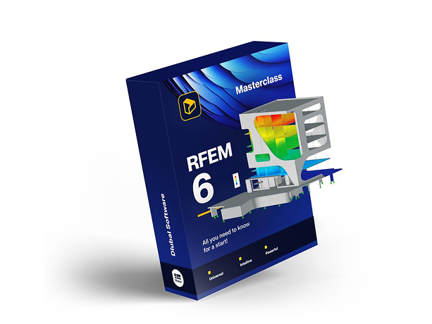
RFEM 6 Masterclass: All you need to know for a start!
A structural analysis course for engineers starting with RFEM 6. It builds a concrete model from base data, materials and thicknesses through nodes, surfaces, columns, beams, openings and supports, then covers load cases, the FE mesh, graphical and tabular results and the printout report, and closes with a steel model worked through the same steps.
Subscribe
- Access to 300 top-rated courses, webinars,...
- Cancel anytime
- Learn more
Buy individual course
Price for language: English
Course rating
Course variant
Recommended skill level
Skills you will gain
- Download, install and license RFEM 6, and find models and templates in the Dlubal Center
- Navigate the menu, toolbar, navigators, tables and control panel of the user interface
- Set up a new model with its base data, materials and surface thicknesses
- Model nodes, lines, surfaces, columns, beams and openings, and copy and divide geometry
- Assign nodal, line and surface supports, and check them in the model
- Create load cases and combinations, and apply surface, line and member loads
- Set the FE mesh target length and add mesh refinements before calculating
- Read graphical results, result sections, support reactions and result tables
- Assemble a printout report with graphics and export it to PDF
- Model a steel base plate with guide lines, end plates and weld seams
This course includes
Modules
2h 36min8 modules28 lessons
- 1min1min
The lesson introduces the RFEM 6 online course, whose aim is basic knowledge of RFEM 6 and simple designs done independently. It recommends modelling alongside the lessons, addresses beginners and anyone refreshing existing knowledge, and points to a free 90 day trial version on the website and a free student version.
- 4min4min
RFEM 6 is downloaded from the Dlubal website's Products to Download tab and installed, setting program language, region and unit system. Licensing is online and account-specific, not computer-bound or named user. A free license is selected, its add-on constellation and borrow option shown, and OK starts the software.
- 2min2min
The Dlubal Center is opened from its symbol in the upper left corner, showing the Models area with the navigator, model previews and the filter into RFEM and RSTAB models, then the Templates section and the Blocks with ready-to-go models. An example is opened with a double click to start the RFEM user interface tour.
- 4min4min
Breaks the RFEM 6 user interface into menu bar, toolbar, navigators, tables, control panel and graphic interface on an open model. Goes through each menu from file to window, then shows the toolbar shortcuts and how a right click opens customize menus and toolbars to add or remove tools.
- 6min6min
Self weight is calculated via Calculate current loading to activate the fourth navigator. The data, display and view navigators are used to search objects, show loads and mesh, save a user-defined view and isolate the IPE 180 members. The results navigator then shows global deformations and support reactions.
- 4min4min
Shows the tables under the RFEM 6 graphical interface for static analysis, loads and structure, plus the two symbols that switch off table-model interaction. It then covers the control panel, display properties, the display cube, selection windows in both directions, scroll-wheel zoom, move and rotate, and snapping.
- 5min5min
A new model is created from the menu File, New: model name, 3D model type, solids deactivated, and two add-ons that create load combinations automatically. The geozone tool imports the Dlubal offices in Philadelphia with their snow, wind and seismic loads, then OK creates the model and prompts for a saving location.
- 7min7min
Grid point spacing is set to 0.5 metres and the intersections and perpendicular anti-parallel object snaps are activated. For the floor slab, a concrete material is imported from the material library and a thickness of 20 centimetres with that material is created. The book, star, hand and arrow symbols are explained.
- 3min3min
A 20 cm concrete floor slab is created with New Rectangular Surface, stiffness type standard, drawn from the origin to the coordinates X 14, Y 12 m. An arc via 3 nodes then bounds a small semicircular surface, whose lines are joined to the slab edge with Connect before it is inserted with Select Boundary.
- 10min10min
Nodes for the columns are copied with Move or Copy, and lines are divided 3.5 m and 8.5 m from line start via Divide Line. The slab is copied -3.25 m in Z, and the two surfaces are replaced by surface 3 with New Surface Based on Boundary Lines and a new 30 cm thickness. New Line then connects the nodes for the walls.
- 2min2min
The walls are inserted with the New Surface tool via Select Boundary, using 20 centimetres thickness and concrete C30/37 confirmed in the New Surface window. One wall is duplicated by holding the control key, and the last wall on the curved surface is created with the Quadrangle command.
- 8min8min
Four methods create the columns in RFEM 6: new single member on the toolbar, a line edited into a member, the data navigator, and the members tab of the structure table. The 35 by 35 centimetre section is defined in the cross-section library, and the column row is then copied by dragging with the control key held.
- 3min3min
A downstand beam between nodes 37 and 35 is drawn as lines and edited into a member of type rib, aligned to the plus Z side of the surface. A new massive rectangle section, 20 centimetres by 15, is created, and rib section is enabled in the display navigator under members to show the effective slab width.
- 5min5min
A circular opening is placed on the ceiling slab: a new node between nodes 4 and 5, a circle of radius 1.8 m, then Select Boundary Lines in the New Opening tool. The work plane is then rotated from XY to XZ so a rectangular opening can be drawn on the wall surface, and reset to XY.
- 4min4min
A line support acting only in Z is created and assigned to two edge lines. A nonlinear surface support for gravel is added to the rectangular and semicircular floor slabs with 10, 10 and 100 MN/m³ and failure of negative contact stresses. The linear support is depicted in green, the nonlinear one in light blue.
- 9min9min
The edit active load case dialog in RFEM 6 checks the self-weight, adds an imposed load case and wind in X and Y, and deletes the characteristic design situations. Two imperfection cases are assigned to the wind load cases. A new rectangle set to stiffness type load transfer forms the load transfer surface.
- 11min11min
New surface load and new line load apply imposed and wind loads: 5 kN/m² on the floor slab, edited to 2 kN/m² on the ceiling slab, 0.4 kN/m² for wind in X, the suction side on projected area. New member imperfection adds relative imperfections in X and Y to the columns, turned by reverse line or member orientation.
- 5min5min
A plausibility check and model check are run in RFEM, the mesh settings keep the default target length of finite elements of 0.5 metres, and Calculate All is started. An FE mesh refinement with a radius of 2 metres is then set on node 34, and the mesh is displayed again and recoloured green in the display properties.
- 4min4min
Calculate all shows the deformations by default. In the results navigator, surface results become isolines and member deformations section colored; the control panel slider hides deformations from 0 to 0.3. Internal forces open from the toolbar, the default 2 colored becoming a diagram with only the extreme values.
- 4min4min
Result diagrams of selected members are opened for a downstand beam, showing global deformations and bending moments for the ULS. A new results section is then set on two nodes in the upper part of the columns, assigned only to slab number three, and selected in the data navigator to display its results.
- 3min3min
Support reactions are activated in the results navigator as actual values or a smooth distribution, contact stresses in the Z direction as a colored transition or gray zone. Principal stress trajectories are shown on the wall, and the table results for the ULS list global deformations, internal forces and surfaces.
- 7min7min
A printout report is created from the data navigator, its content and print setup defined in the printout report manager. Model views, load cases and results are added as graphics via print graphics to printout report with multiprint. The report language is set from 11 languages before export to PDF.
- 5min5min
A new 3D steel model in RFEM 6 gets the combination wizard deactivated, 10 centimetre grid point spacing and millimetre lengths. A uniform 50 millimetre thickness in steel S 235 is created, and new rectangular surface draws the base plate on the origin. Including thickness is then switched on in the display navigator.
- 7min7min
Openings > Circle cuts a 20 mm radius hole in the base plate at a node copied with Move/Copy, and Rotate copies it in 3 steps of 90 degrees about a node made Between 2 Nodes. Copy with Link Nodes with Line, Ctrl drag-and-drop and Mirror about the YZ plane then build the full HEB cross-section lines for the surfaces.
- 6min6min
Two methods create the surfaces of an HEB 200 in RFEM 6. The first copies the nodes -1000 mm in Z with Link lines with surface, then sets 15 mm flanges and a 9 mm web in S235. The second copies the middle node with Link nodes with member and runs Generate surfaces from member for the same result.
- 3min3min
New Rectangular Surface at stiffness type rigid adds the end plate on top of the surfaces to apply the loads without singularity effects. The base plate gets a nonlinear support: spring 1.5 × 10⁵ in Z, failure of negative contact stresses. Assign Line Support adds hinged supports on four lines around the openings.
- 7min7min
Self-weight and H load cases are created by hand in the load cases and combinations window and dragged into a new load combination, 1.35 for the self-weight. Nodal loads of 20, -200 and 40 kN follow and mesh settings drop the target length to 20 mm. The FE mesh shows the opening refinements and 1 mm at the weld seam.
- 5min5min
Calculate all computes the model; deformations, basic stresses, the deformation animation and support reactions are reviewed, and iso bands are switched to iso lines. A new section through the welding line is assigned to the base plate, and its bending moments open in result diagrams for selected result sections.
Who this course is for:
- Structural engineers taking their first steps with RFEM 6
- Engineers moving to RFEM 6 from another structural analysis package
- Students and recent graduates learning finite element modelling of buildings
- Draftspeople and technicians who prepare models for engineers to verify
- Anyone refreshing existing RFEM knowledge before working on a live project
Application areas:
Industry:
Standards:
Role:
Product:
Meet your coach

Dipl.-Ing. Praxitelis Dimitriadis
Marketing Manager
Praxitelis manages video marketing and social media content. He also oversees the Online Learning Academy and its ongoing development.


Related Courses





€299.00


