
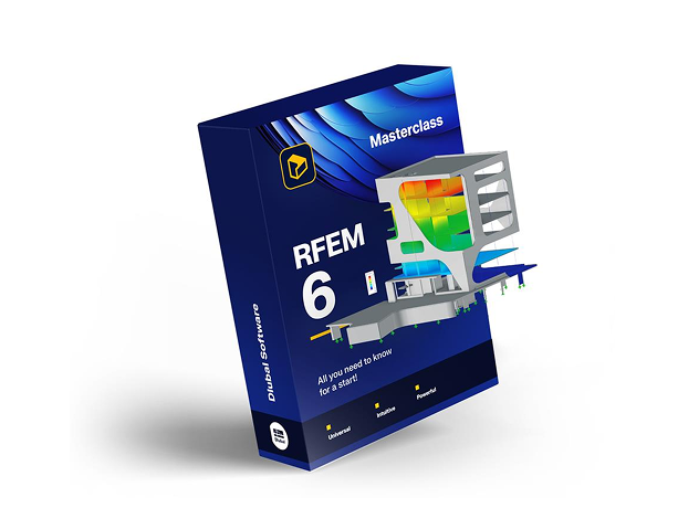
Masterclass RFEM 6: All you need to know to start!
A structural analysis course for engineers starting with RFEM 6 in US practice. It builds a concrete model from base data, materials and thicknesses through nodes, surfaces, columns, beams, openings and supports, then covers load cases, stiffness modifications, the FE mesh, graphical and tabular results and the printout report, and closes with a steel base plate worked through the same steps.
Subscribe
- Access to 300 top-rated courses, webinars,...
- Cancel anytime
- Learn more
Buy individual course
Price for language: English (US)
Course rating
Course variant
Recommended skill level
Skills you will gain
- Download, install and license RFEM 6, and find models and templates in the Dlubal Center
- Navigate the menu, toolbar, navigators, tables and control panel of the user interface
- Set up the base data of a new model and place it on the map with the Geo-Zone Tool
- Create materials and thicknesses from the US material library in imperial units
- Model nodes, lines, surfaces, columns, beams and openings, and copy and divide geometry
- Assign nodal, line and surface supports, including nonlinear supports on a gravel bed
- Generate LRFD and ASD load combinations with the combination wizard and apply loads
- Apply ACI 318 stiffness modification factors to concrete members, slabs and walls
- Set the FE mesh target length and add mesh refinements before calculating
- Read graphical results, result sections, support reactions and result tables
- Assemble a printout report with graphics and export it to PDF
- Model a steel base plate with guide lines, end plates, weld seams and its own load cases
This course includes
Modules
2h 42min8 modules29 lessons
- 1min1min
Alex introduces the RFEM 6 basics course, explaining its goal of giving a working knowledge for simple designs and encouraging viewers to model alongside him. He notes the free 90 day trial and the free student version for those without RFEM 6 yet.
- 5min5min
The video downloads RFEM 6 from the products to download tab, then runs the installer, choosing language, region and unit system before logging in with Extranet credentials. It closes on the new online licensing: cloud based through the Extranet account with no USB keys, plus borrowing and returning a license.
- 4min4min
The Dlubal Center tour moves from the model section, with its project navigator and bitmap area, through the template section to the block section. A double click there opens the edit blocks dialog box for sections and materials, and clicking okay places the Dlubal Center steel hall example in RFEM.
- 3min3min
The RFEM 6 interface is broken into menu bars, toolbars, navigators, tables and the control panel, then each menu from File through Window is covered, noting Results stays grayed out until a calculation runs. It closes on the toolbar's shortcuts and customizing it by right clicking to select customized toolbar.
- 5min5min
The data, display and views navigators are covered, and a results navigator appears once calculate current loading computes the self weight. Used items read black and unassigned blue, a user defined view is saved and visibility limited to the W18X86, and results list global deformations and support reactions.
- 4min4min
The tables switch between the static analysis, load and structure tables, and two symbols disable the table to model and the model to table interaction. The graphical interface then covers display properties backgrounds, the display cube, scroll wheel zoom, pan and rotate, and the grid snap options at the bottom.
- 4min4min
In the New dialog, the model is named concrete model and set to a 3D structure, with Solids deactivated under Main Objects. The Add-ons tab activates Standards for classification and wizards, then the Geo-Zone Tool sets the location to the Dlubal office in Philadelphia, Pennsylvania before OK creates the model.
- 4min4min
The work plane grid, line connection and object snaps are set before the top down view. New material takes United States, concrete, ACI 318 2019, 4000 PSI from the library, and new thickness keeps eight inches with that material assigned. A rectangular surface from the origin to 46 feet, 40 feet generates the slab.
- 2min2min
Arc via three nodes draws the boundary line for a semicircle from the top node through X 53, Y 33 to X 46, Y 26. The arc and the large slab's boundary line are joined with connect, which splits that line in two, and select boundary line creates the surface with the same settings, finishing the floor slab.
- 7min7min
A node is copied through right click, manipulation, copying by 2 feet in X and Y, then move/copy repeats it 16 feet in X and 13 feet in Y for four rows of columns. Lines are divided at 12 feet and 18 feet, the slab is copied 11.83 feet in Z, and the top surface is rebuilt at 12 inches before lines join nodes 5 and 24.
- 3min3min
Walls are inserted with the new surface tool and the boundary lines option, keeping the 4000 PSI concrete material and the 8 inch thickness. The connect selected lines tool joins the structure's lines, one wall is copied by dragging it onto a node with control held, and the curve section uses the quadrangle tool.
- 5min5min
Four methods create the columns in RFEM: the new single member tool, a line with the member checkbox, the data navigator, and the structure table. Each column is a classic beam, massive rectangular section, concrete 4000 PSI, 14 by 14 inches. Copy and paste, dragging with the control key held, duplicates the row.
- 4min4min
The dialog builds a downstand beam between nodes 37 and 35 through the Edit Line box, setting member type Rib on the negative Z side and a 12 by 12 inch parametric section. Checking Rib Section in the display navigator renders the effective slab width flanges, completing all members in the structure.
- 4min4min
A circular opening is drawn in the ceiling slab around new node 43, made between nodes 24 and 22, with a radius of 6 feet. The workplane origin is then set to node 19 in the XZ plane for a rectangular opening on the back wall, then reset to XY. Each opening gets an index number under Openings in the data navigator.
- 6min6min
Assign New Line Support creates a line support with X and Y released and Z fixed on lines one and seven. Surfaces one and two get a nonlinear gravel support: 64 kips per cubic foot in X and Y, 640 in Z, 32 kips per foot in shear, failure if positive contact stress in Z. Linear supports are green, nonlinear light blue.
- 7min7min
Opens the Edit Load Case window to set self weight to dead and creates live, wind X, and wind negative Y load cases, with wind loads set to act alternatively. Reviews the LRFD and ASD design situations and load combinations, then builds a load transfer surface on an opening using selected boundary lines.
- 10min10min
Turns on the self weight display, then uses New Surface Load to apply live loads of negative 0.1 k per square foot on the floor slab and 0.04 kip per square foot on the ceiling slab. Adds wind X and wind Y surface and line loads, including a 0.05 kip per foot line load on lines 8 and 16, correcting direction and sign.
- 6min6min
Under the strength design situation, creates a combination wizard set to 2nd order and activates structure modification. Assigns ACI 318-19 Table 6.6.3.1.1(a) to the columns and rib member, uncracked to the walls and flat plates and flat slabs to the slabs. Renames the combination second order reduction.
- 6min6min
Runs the plausibility check, then the model check for crossing or unconnected members and for identical nodes, and keeps the default 1.5 feet target length in mesh settings before Calculate All. Adds an FE mesh refinement of 5 feet radius at node 34, regenerates the mesh and turns it green under display properties.
- 7min7min
After Calculate All in RFEM 6, envelope deformations for the ultimate limit state combination are displayed, with the surface display changed from isobands to isolines and to wire frame. Internal forces are then reviewed on members and surfaces, the member results set to a diagram with hatching.
- 5min5min
In RFEM 6, Result Diagrams for the selected downstand beam show the strength limit state design situation, with any value readable at any point. Set New Results Section then cuts the ceiling slab, slab number 3, between two points, and the section deflection is plotted in the X Z plane.
- 4min4min
In RFEM, support reactions are activated in the results navigator, with actual values switched to a smooth distribution, and Sigma Z contact stresses turned on for surfaces. The results tables give max displacements and rotations, sync results on members with the graphical view, and can be exported to Microsoft Excel.
- 8min8min
In RFEM, a new printout report is created from the data navigator and its content picked in the printout report manager, where print setup offers a logo and client name. Print Graphics adds model images by load case and results, the report language is set under edit from 11 languages, and Export to PDF saves the file.
- 6min6min
Creates a new 3D model named steel model with the combination wizard deactivated and model length set to inch. Adds Steel A36 from the Material Library (AISC 360-22) and a uniform 2 inch thickness, then draws a 20 by 20 inch rectangular base plate. Filled thickness display is shown as an option and left as filled.
- 5min5min
Copies a corner node 4 inches in X and Y, places a circular opening of 0.8 inches there, and rotates three copies 90 degrees about the Z axis into the other corners. Links the new nodes with lines using step links, then mirrors them about the YZ plane to form the W shaped section.
- 7min7min
Copies the lines and nodes 40 inches in Z and uses step links to link them with surfaces from a W 8 by 31, with 0.44 inch thicknesses and a 0.31 inch web in Steel A36. A second method links a copied center node with a beam member in Steel A992, then runs generate surfaces from member to avoid a singularity.
- 3min3min
Adds a rectangular surface with rigid stiffness atop the member, then gives the base plate a surface support active only in translational Z, with a 500,000 kip per cubic foot spring constant and failure if positive contact stress. Hinged line supports go on the edges of the openings, acting at every FE mesh point.
- 7min7min
Keeps the default load case and adds a live load case, combined with partial safety factors of 1.4 for self-weight and 1.0 for live load, applying 5 kips and 50 kips, plus 4 kips, as nodal loads. The default 18 inch mesh is set to one inch, with refinement at openings and a 0.2 inch line refinement along the weld seam.
- 8min8min
Runs calculate all, then reviews global deformations, surface forces, and contact stresses on the base plate, where areas stay blank under uplifting forces. It checks support reactions and deformation animation, then draws a results section through the weld line with Object Snap, showing the MX bending moment.
Who this course is for:
- Structural engineers in the United States taking their first steps with RFEM 6
- Engineers moving to RFEM 6 from another structural analysis package
- Engineers who work in imperial units and design to US codes
- Students and recent graduates learning finite element modeling of buildings
- Draftspeople and technicians who prepare models for engineers to verify
Application areas:
Industry:
Standards:
Role:
Product:
Meet your coach

Alex Bacon, EIT
Support Engineer
Alex handles customer training and technical support for the North American market and works on continued program development.


Related Courses





€299.00


